ER Diagram
ER Diagram stands for Entity Relationship
ERD is a diagram that displays the relationship of entity sets stored in a database. In other words, ER diagrams help to explain the logical structure of databases. ER diagrams are created based on three basic concepts: entities, attributes and relationships.
ER Diagrams contain different symbols that use rectangles to represent entities, ovals to define attributes and diamond shapes to represent relationships.
R diagram looks very similar to the flowchart. However, ER Diagram includes many specialized symbols, and its meanings make this model unique. The purpose of ER Diagram is to represent the entity framework infrastructure.
ER Model
ER Model stands for Entity Relationship Model is a high-level conceptual data model diagram. ER model helps to systematically analyses data requirements to produce a well-designed database. The ER Model represents real-world entities and the relationships between them. Creating an ER Model in DBMS is considered as a best practice before implementing your database.

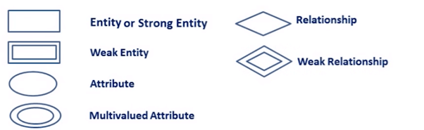
ER Diagram Symbol
- Rectangles: This Entity Relationship Diagram symbol represents entity types
- Ellipses : Symbol represent attributes
- Diamonds: This symbol represents relationship types
- Lines: It links attributes to entity types and entity types with other relationship types
- Primary key: attributes are underlined
- Double Ellipses: Represent multi-valued attributes
Components of the ER Diagram
- Entities
- Attributes
- Relationships
Usages of ER Diagram
- ER model allows you to draw Database Design
- It is an easy to use graphical tool for modeling data
- Widely used in Database Design
- It is a GUI representation of the logical structure of a Database
- It helps you to identifies the entities which exist in a system and the relationships between those entities


No comments:
Post a Comment